⚡ Ignition Timing Control for Sniper EFI on Isuzu 2.3L(4ZD1)
Background and Problem Statement 🤔
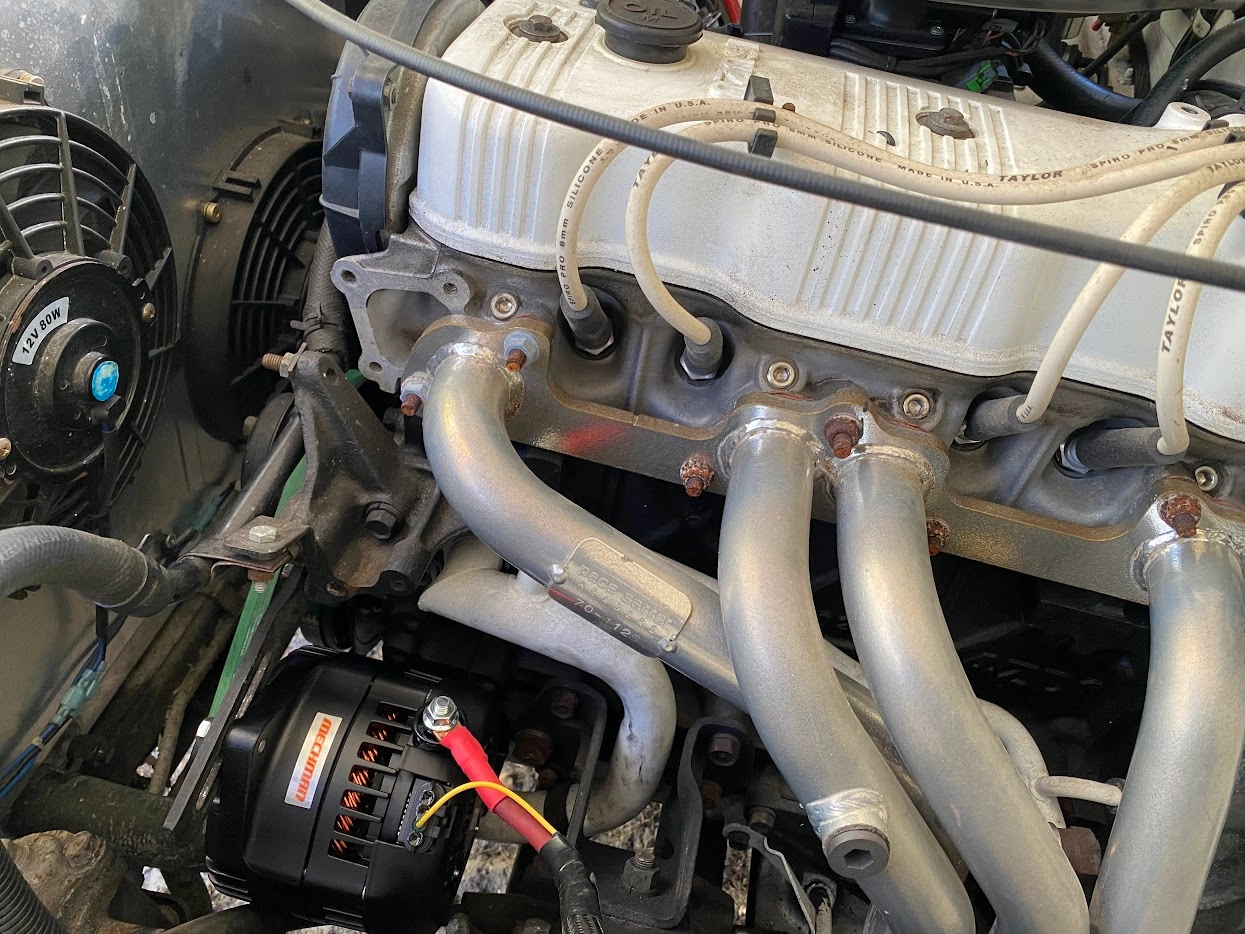
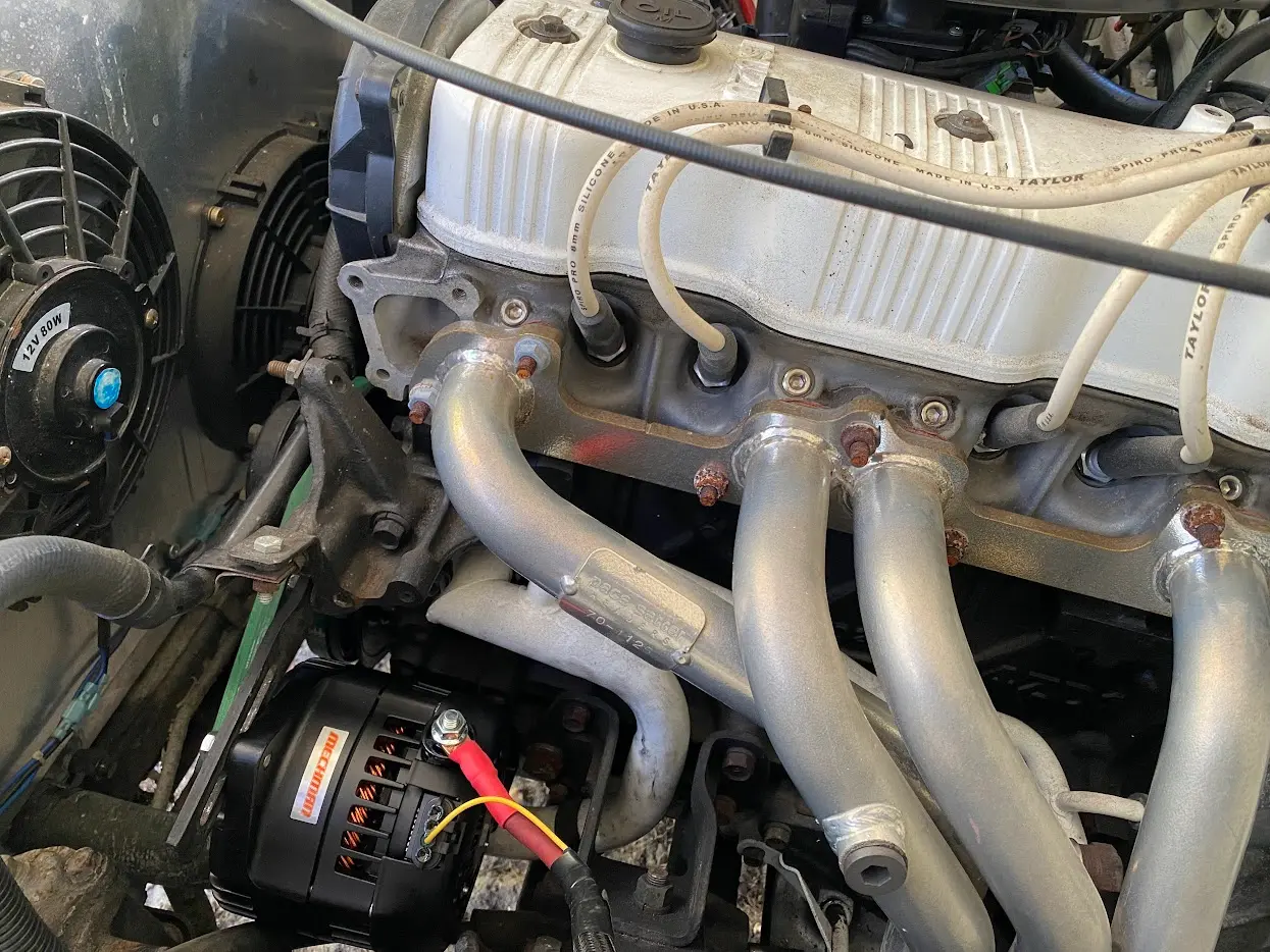
The Isuzu 2.3L 4ZD1 engine was released as a SOHC engine produced from 1986 to 1995. The version included in the 86-87 Trooper did not come with the option of electronic fuel injection. That was introduced with the 2.6L 4ZE1 motor.
Aftermarket EFI systems such as the Holley Sniper EFI can be added with some fuel system modifications, custom adapters, linkages, and wiring. Magnetic pickup distributors are supported with Sniper EFI to allow for computer controlled ignition timing, however, the stock magnetic pickup distributor poses a limitation with the Holley Sniper setup. Normally, magnetic pickup distributors contain a simple wire coil that picks up the induced voltage when the reluctor rotates past the pickup, sending the raw voltage spikes to the ignition control system.
The 2.3 distributor has 2 wires attached, and uses a special pickup that contains the wire coil along with a transistor-based amplifier circuit. One of the wires comes from the vehicle’s 12V ignition positive to drive the transistor circuitry. The other functions as the trigger output, and emulates a points-style distributor. As it rotates it pulls the ground side of the ignition coil low, building a magnetic field. When the output returns to its high state, the magnetic field collapses and a spark on the ignition coil secondary is created.
This means we are forced to set up our Holley Sniper EFI with a points trigger input. Unfortunately, this mode of operation does not allow for control of the ignition timing from the Sniper. Timing control is achieved using the stock vacuum advance configuration.
Limitations 🚧
A non timing-controlled EFI setup is completely acceptable and according to Holley is quite common. However, there are some side effects with this configuration. One of the major issues I noticed was an unstable idle that ‘hunts’ to maintain the target RPM. This is where the Sniper is using the Idle Air Control Valve (IAC) to manage engine RPM by controlling airflow at idle. The IAC often overshoots the target RPM, and then overcompensates the return. With enough time spent dialing in your Air Fuel Ratio (AFR) and limiting closed loop fueling adjustments, you can get a ‘mostly’ steady idle.
The second issue is ‘stumbles’ or stalls when coming back to idle from certain conditions such as deceleration. The IAC itself is sometimes unable to catch the falling engine RPM before it reaches a stall condition.
How Timing Control Can Help 🤝
Ignition timing controlled by the Engine Control Unit (ECU) can drastically help with the above limitations. In our case, our Sniper EFI is capable of filling the role of the traditional ECU. Adjustments to engine timing helps manage torque, which in turn allows us to control engine RPM in addition to fueling and air. The major benefit to using ignition timing to control RPM at idle is how fast changes in timing can be performed compared to using on the IAC. These fast changes can eliminate hunting at idle, as well as help to catch falling engine RPMs before the engine reaches a stall condition.
Beyond that, timing control can let us increase fuel efficiently and power throughout the engine’s operating range.
Trial and Error ⛓️💥
The first attempt I made to enable timing control was less than successful. The idea was that the ignition pickup still contained a coil of wire just like those found in a lot of other vehicles. If I were to remove the extra amplifier circuitry from the distributor pickup and attach directly to the 2 ends of the coil, that would in theory provide a pulsed waveform that the Sniper or even a MSD Capacitive Discharge (CD Box) should be able to read. Combine that with removing the vacuum advance and locking out (by welding) the plate inside the distributor to keep it from advancing on its own, we should be able to use the stock distributor.
Despite the attempt, I was unsuccessful at getting this setup to work. Looking at the output waveform on an oscilloscope, the signal was just a few millivolts and not enough to trigger either the Sniper, or MSD box’s magnetic pickup input.
Back to the Drawing Board 🔄
I had a shower thought about using the distributor out of the fuel injected 4ZE1 (2.6L) motor as they are fairly common, mount to the 2.3L cylinder head, and have a Hall Effect pickup which is desirable for accurate timing control with EFI.
After doing some research and looking at salvage parts resellers online, I settled on the 2.6L distributor for the 1988-1991 year range. This distributor has a 4-pin square connector on the base of it. The later year EFI distributors have a 4-pin connector as well, but it’s rectangular and protrudes from the side of the unit. I’m not certain as to whether that model is electrically compatible with this style or not. If anyone has the answer to that, let me know in the comments down below.
Testing and Harness Creation 🧪
Searching online forums, and utilizing ChatGPT’s Deep Research mode, I was able to come up with a pretty good idea of the distributor pinout.
These are the wire colors that were identified in the harness.
| Color | Purpose |
|---|---|
| Black | Signal Ground |
| Red | 12V Sensor Power |
| Green | 1 Pulse Per Degree (Active Low) |
| White | 1 Pulse per 90 Degrees (Active Low) |
To confirm the assumptions on the pinout, a bench test was performed using a PC power supply to provide 12/5VDC.
| Color | Connection |
|---|---|
| Black | Power Supply Ground - Oscilloscope ground |
| Red | Power Supply +12V |
| Green | Power Supply +5V (via 10KOhm Resistor) - Oscilloscope blue probe |
| White | Power Supply +5V (via 10KOhm Resistor) - Oscilloscope yellow probe |
Wiring configuration:
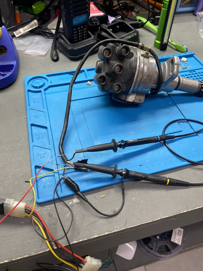
Turning the distributor by hand while performing a capture shows the output pulses to ground.
The inconsistency in width of the pulses is due to rotating the distributor by hand instead of at a fixed RPM.
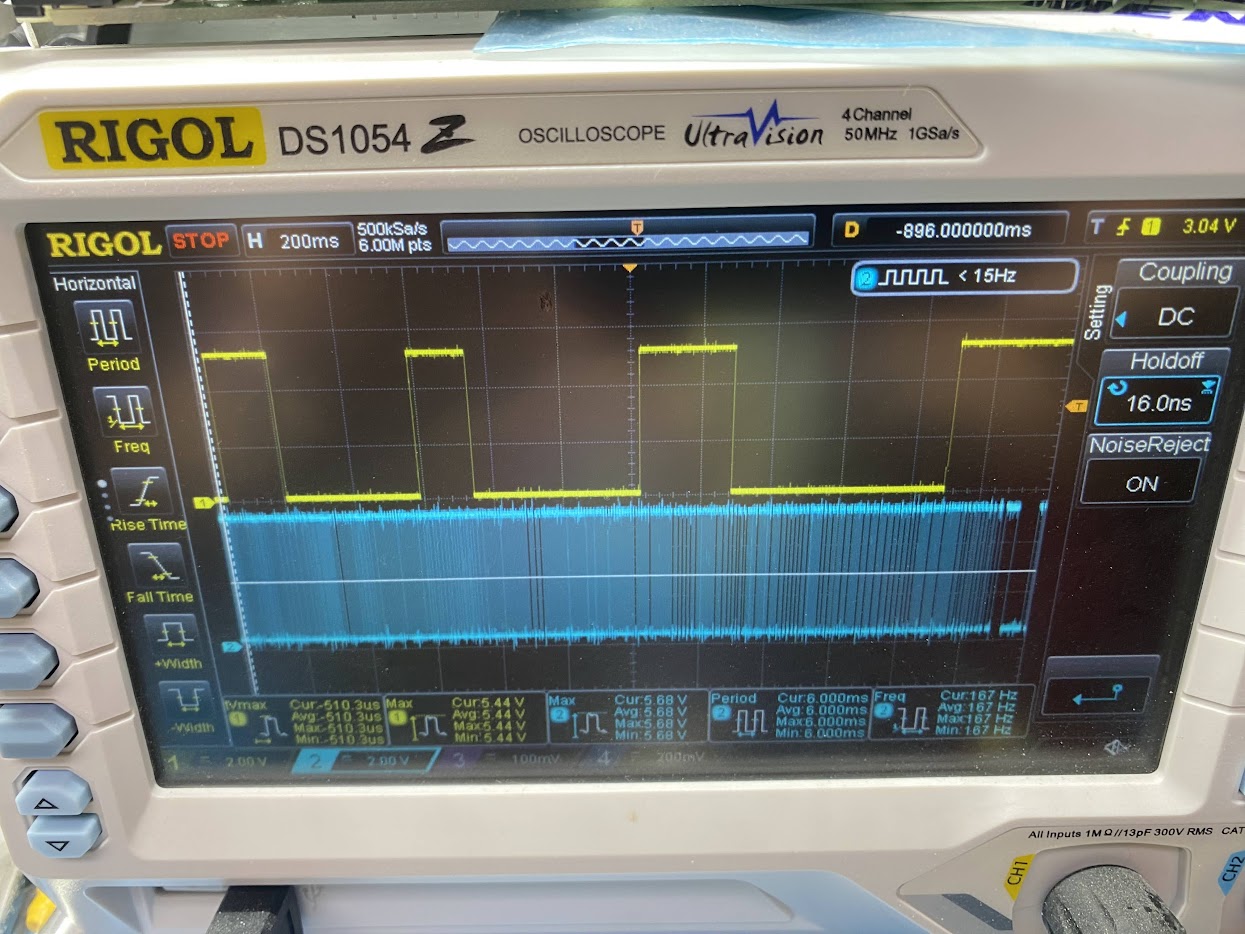
The White wire is confirmed to provide the single rising and falling edge for each cylinder, which is what we need as the trigger.
Vehicle Wiring 🚗
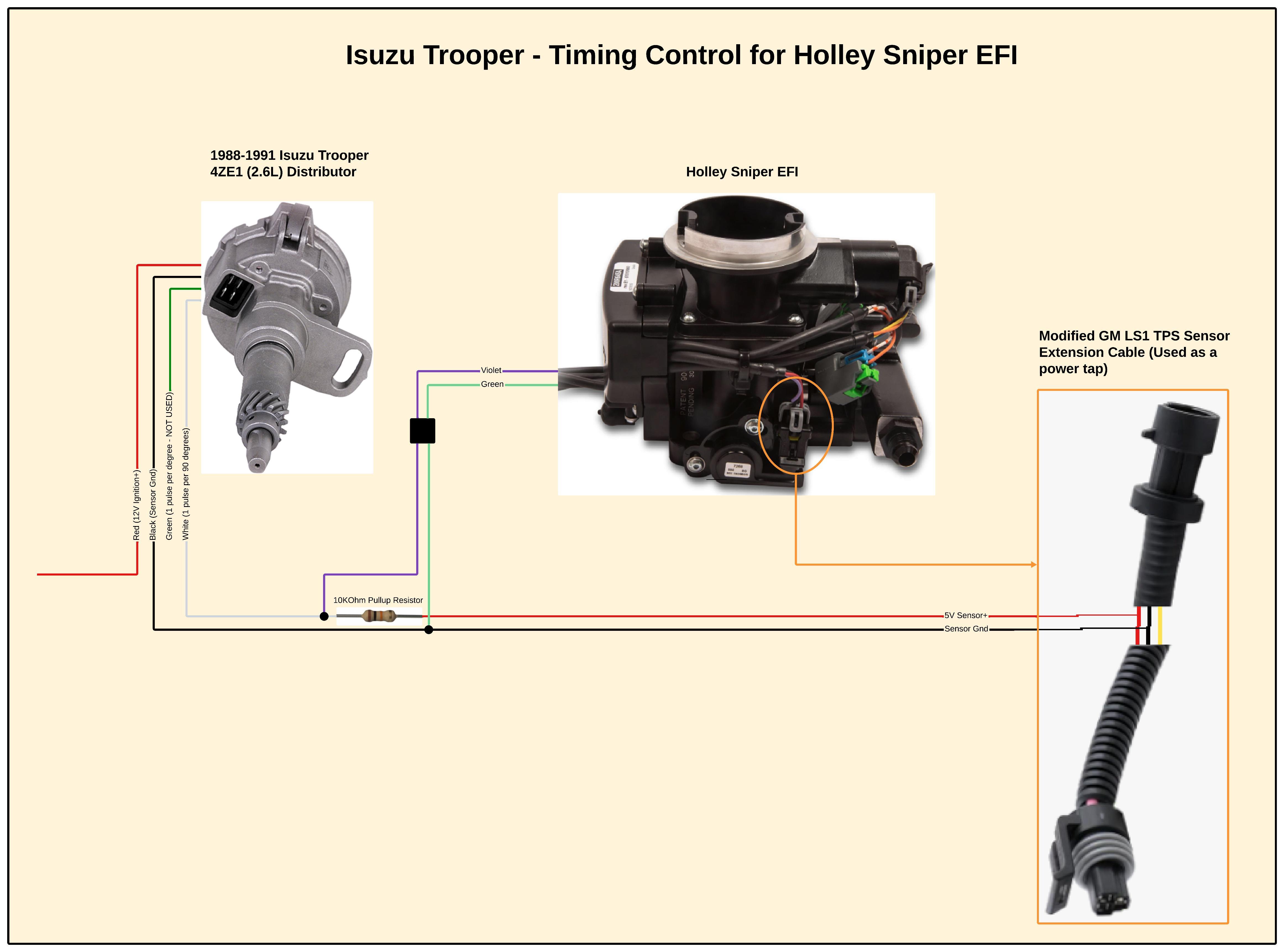
On the vehicle, the wiring is fairly straightforward, with one exception. The sensor needs a 5V reference to hold the voltage high between pulses. I needed to find something close to the distributor with an accurate 5V reference to tap into. The Sniper EFI has a Throttle Position Sensor (TPS) that is easy to get to on the side of the unit. This TPS uses a standard GM LS1/LS6 3-pin connector, with one of the pins providing a constant 5V. With a 10KOhm resistor to ground, the current draw added by the pull-up resistor is <1mA. This should not be enough of a current draw to interfere with the TPS operation. We can modify a TPS extension cable to use as a power tap to avoid modifying the wiring on the Sniper. We will unplug the current connector from the TPS, and insert our extension cable in between.
Our finished wiring schematic is as follows:
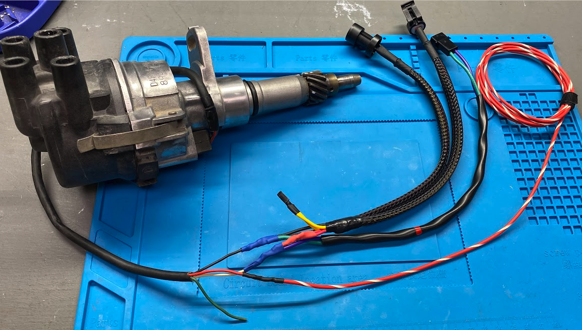
We can create a clean harness for the distributor that allows us to easily connect and disconnect it.
Finishing Up 🏁
Physical installation and tuning configuration is outside the scope of this blog post, but resources can be found online.
At a high level, these are the final steps:
- Physically install the distributor at cylinder 1 TDC
- Connect all wiring connections
- Set the
Ignition TypetoHolley Dual Sync - Set the
Reference Angleto50degrees - Enable
Idle Spark Control - Configure your
Simpleor2Dtiming table as desired - Test drive and data log
← Back to blog